- Double crystals
- Double multilayers
- VFM1 & VFM2
- HFM1 & HFM2
- VDM
- 4-bounce channel collimator (4BCC)
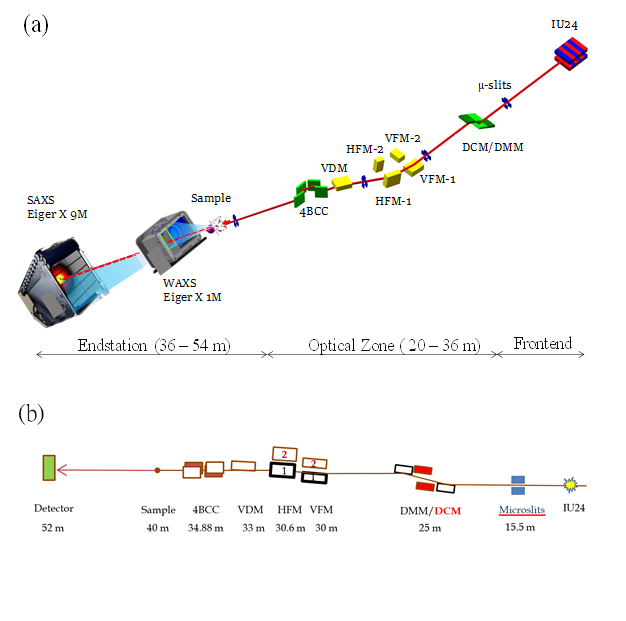
(a) 3D drawing and (b) a side view of the primary optical components and beam path of the TPS 13A BioSAXS beamline. Starting from the right are the undulator IU24, microslits, DMM/DCM, two parallel sets of vertical/horizontal K-B focusing mirrors (VFM 1-2 and HFM 1-2), vertical deflecting mirror (VDM), and four-bounce double-crystal collimator (4BCC). Located in the endstation zone are the sample stage and the detecting system comprising Eiger X 1M for WAXS and Eiger X 9M for SAXS data collections.
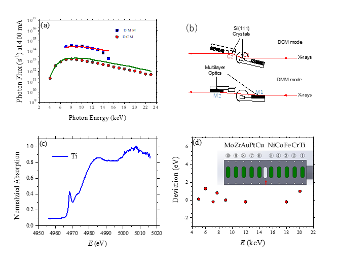
(a) DMM/DCM flux spectra measured at the sample position (40 m from the IU24), with an electron beam current of 400 mA. The spectra are fitted decently with the calculated spectra (solid curves). (b) Schematic view of the dual monochromators DMM/DCM, with the rotating center of the whole system situated at the center of the first Si(111) crystal. The rotation ranges of the DMM/DCM platform from 0.965°- 2.068° is for 15 – 7 keV beam with DMM, and 4.93° - 29.62° for 23 – 4 keV with DCM. (c) A typical absorption spectrum of a standard Ti foil taken with the DCM. (d) Accuracy of the beam energy defined by the DCM after calibration with the 10 in-vacuum standard foils (inset) deployed at the downstream of the DMM/DCM.
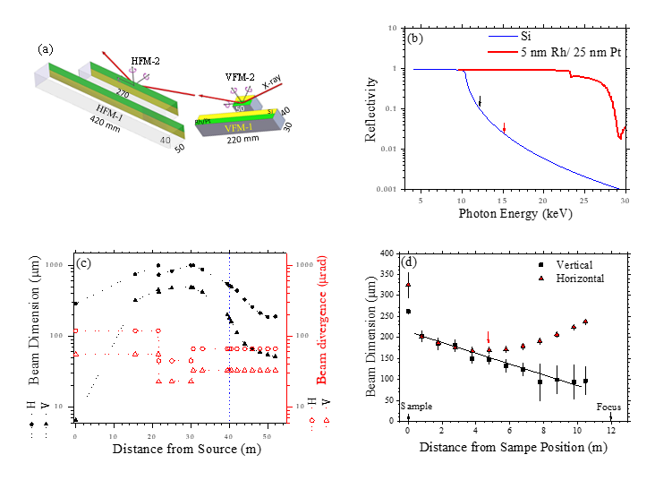
(a) The twin focusing system comprising two sets of vertically and horizontally focusing mirrors (VFM and HFM) made of Si crystal blocks with the indicated dimensions. Half of each mirror surface is coated with Ru/Pt bilayers (colored in green) for enhanced reflectivity of high-energy X-rays; the rest half remains bare Si surface (yellow). (b) Calculated X-ray reflectivity of the bare Si surface and Pt/Ru-coated surfaces of the focusing mirrors. (c) Simulated beam size and divergence (FWHM) over the whole beam path. (d) Measured evolution of the beam size from the sample position to the beam focus, using a 10-keV DCM beam and the Eiger X 9M detector. The beam size 280 mm (H) ´ 50 mm (V) extrapolated (solid line) to the focus position is consistent with the simulated one shown in (c). Note that the beam size at the 52-m focus could not be measured due to a length limit (14 m) of data transmission cables of the Eiger X 9M detector in vacuum.
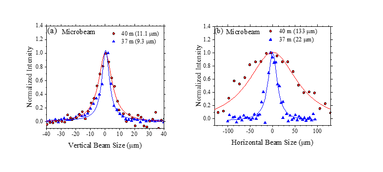
(a) Vertical and (b) horizontal beam profiles of a 15-keV microbeam with DCM and the sample-focusing K-B mirrors measured at 37-m and 40-m positions, using an opening of 10 mm ´ 10 mm of the microslits. The fitted beam dimensions (FWHM) are indicated in the brackets.
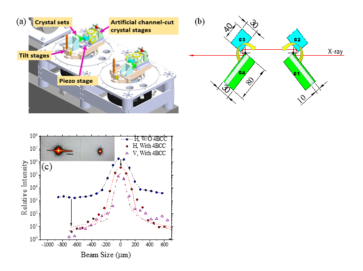
(a) 3D drawing of the 4-bounce crystal collimator 4BCC (situated at 34.88-m position), comprising two sets of double crystals of Si(111) or Si(311) situated respectively on two large rotating stages for a dispersive configuration. Each of the crystals is actuated with the three motor stages indicated for independent or coupled motions. (b) An action mode of the 4BCC with the photon beam passing through the 4 crystals of the 4BCC. With 4BCC rotations (indicated by the arrows), X-ray could bypass 4BCC, through the two 80-mm long channels in crystal C1 and C4. (c) Horizontal and vertical beam profiles of a DCM 8-keV beam measured at 49.5 m near the 52-m focus, without (2D image to the left, inset,) and with (2D image to the right, inset) the 4BCC with Si(111). Note that the background scattering intensity near the primary beam is decreased by ca. two orders of magnitude (long arrow) with the 4BCC, at a cost of 10-fold decay in beam intensity (show arrow).
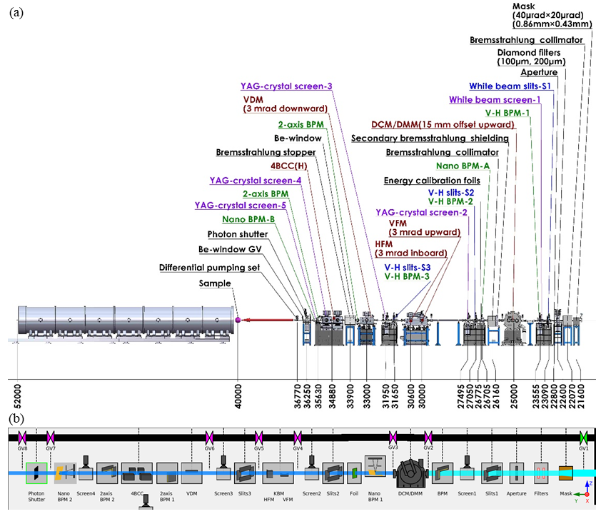
(a) Layout of the optical zone (21 m to 37 m) and the endstation (37 - 55 m) of the TPS 13A beamline. (b) the CSS view of the optical zone. Relevant control dialogue box would appear upon double-clicking the corresponding icon. VDM is for vertical deflection mirror and BPM for beam position monitor.
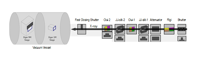
A CSS graphic view (not to scale) of the endstation zone, comprising (from the right) the primary components. The left-hand-side is the detecting system with the two Eiger detectors X 1M and X 9M moving in a large vacuum vessel, of 12 m in length and 1.5 m in diameter, for ca. 10 m travelling distance along the beam path at a speed of 0.5 m/min. The shortest camera distances are 710 mm and 180 mm for the two detectors, respectively. The Eiger X9M could move ±120 mm in the lateral and vertical directions, respectively, and is equipped with a 4-mm beamstop.
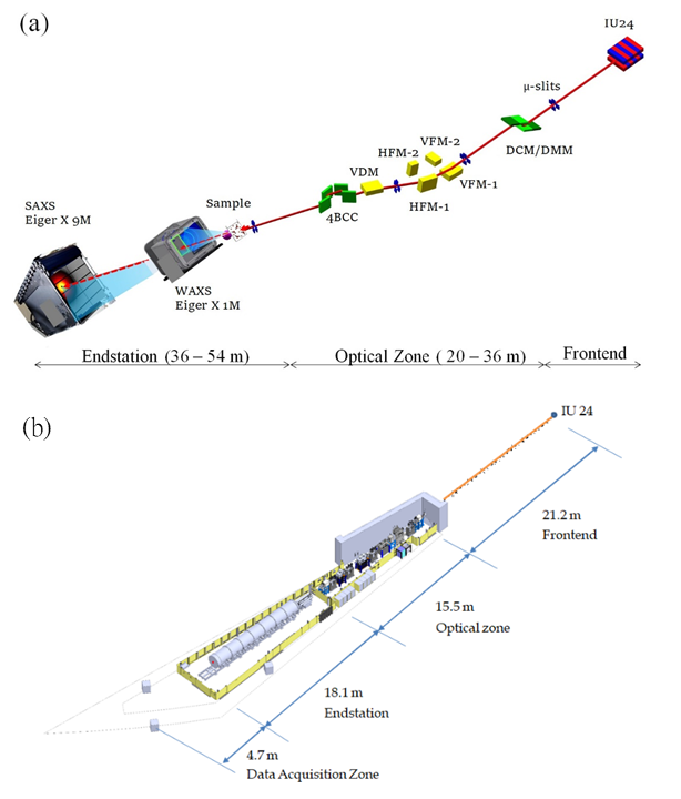
(a) 3D drawing of the primary optical components and beam path of the TPS 13A BioSAXS beamline. Starting from the right are the undulator IU24, microslits, DMM/DCM, two parallel sets of vertical/horizontal K-B focusing mirrors (VFM 1-2 and HFM 1-2), vertical deflecting mirror (VDM), and four-bounce double-crystal collimator (4BCC). Located in the endstation zone are the sample stage and the detecting system comprising Eiger X 1M for WAXS and Eiger X 9M for SAXS data collections. (b)The layout of the TPS 13 beamline, starting from the in-vacuum undulator (IU24) in the front-end, followed by the optical zone, endstation hutch, and the data acquisition zone.